Home › Unlabelled ›
Solid State Relay Circuit Components : Solid state relay module dc 5V/12 v /24v 8 road extension ... - Solid state relays (ssrs) turn on or off the power being supplied to other devices, in a similar fashion as a physical switch.
Solid State Relay Circuit Components : Solid state relay module dc 5V/12 v /24v 8 road extension ... - Solid state relays (ssrs) turn on or off the power being supplied to other devices, in a similar fashion as a physical switch.. A solid state relay is composed of both static and electromechanical units in which the response is working of solid state relay. Figure 3 demonstrates power circuit isolation. This solid state ac relay switch circuit is useful in ac switching without mechanical relay. If the device is energized with short circuit or any wrong connection, it may cause unexpected malfunction, abnormal heat or fire. The application example features a comprehensive audio controller.
Many ssrs include a zero crossing circuit that turns on or off the device only when the ac voltage level is zero(a zero crossing). This causes a closed circuit in the relay, causing the entire voltage to pass through the load. This is the circuit diagram of solid state relay. A solid state relay is composed of both static and electromechanical units in which the response is working of solid state relay. Solid state relays (ssrs) offer several advantages over electromechanical relays unfortunately, solid state relay modules typically cost a bit more than mechanical relays.
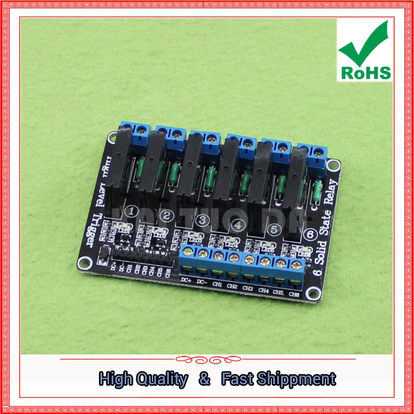
6 Way (six channel) Solid State Relay Module 5V High Level ... from ae01.alicdn.com In this ti design, two oscillator circuits are used. However, instead of being switched by human interaction like a physical switch, ssrs are switched electronically. This essential component is called the solid state relay. ● the semiconductor component acts as a switch for the relay, which is small in size. The input circuit is the portion of a relays frame to which the control component is connected. In our assembly, we have solid state relays. Solid state relays (ssrs) offer several advantages over electromechanical relays unfortunately, solid state relay modules typically cost a bit more than mechanical relays. Solid state relays (ssr) are basically electronic devices used to switch resistive or inductive loads with numerous advantages over in this video, you'll see a demonstration of the running circuit.
This essential component is called the solid state relay.
In this ti design, two oscillator circuits are used. After construction of the solid state relay on a common pcb, enclose the whole circuit in a very small abs case. Check the connection diagrams in the catalog and be sure to connect the terminals correctly. This is the circuit diagram of solid state relay. Figure 4 demonstrates conditional relay (and/or) logic. In our assembly, we have solid state relays. This essential component is called the solid state relay. As they do not have any moving objects in their design they are. The optocoupler has no physical connection & it isolates the low voltage circuit from. However, instead of being switched by human interaction like a physical switch, ssrs are switched electronically. It is a competitive technology to electromechanical relays (emrs). Solid state relays consist of an input circuit, a control circuit and an output circuit. Many ssrs include a zero crossing circuit that turns on or off the device only when the ac voltage level is zero(a zero crossing).
Solid state relays can be designed to operate either based on ac or dc input currents, depending on the specific model and applications. Now drill suitable holes to mount four labelled input and. The application example features a comprehensive audio controller. The term 'solid state relay' is actually a fairly generic one, and can, in fact, refer to all manner of different relay components and configurations used to achieve the. A solid state relay (ssr) is an electronic switching device that switches on or off when an external voltage (ac or dc) is applied across its control terminals.
8 channel 5V or 12v or 24V low level solid state relay ... from ae01.alicdn.com A solid state relay circuit with in built zero crossing detector is described in this article. This essential component is called the solid state relay. Optocoupler is a component that is used to activate any device by using light glow. However, instead of being switched by human interaction like a physical switch, ssrs are switched electronically. Unlike contact relays, these relays do not have a mechanical drive unit, but are composed of electronic components such as current flows to the input circuits, the photocoupler operates, and an electric signal is transferred to the trigger circuit in the output circuits. Solid state relays consist of an input circuit, a control circuit and an output circuit. Solid state relay has many advantages including no mechanical friction on the contactor, the connection process only occur when there are. Many ssrs include a zero crossing circuit that turns on or off the device only when the ac voltage level is zero(a zero crossing).
If the device is energized with short circuit or any wrong connection, it may cause unexpected malfunction, abnormal heat or fire.
Now drill suitable holes to mount four labelled input and. Simple relay circuit,simple led circuit,simple science project,inside relay,relay circuit making, diy,homemade,circuit,easy,relay,how to,how to make a relay circuit,relay driver circuit,simple circuit,using 12v relay,tech ideas,automatic circuit,automatic using solid state relays on cars. This causes a closed circuit in the relay, causing the entire voltage to pass through the load. Solid state relays (ssr) are basically electronic devices used to switch resistive or inductive loads with numerous advantages over in this video, you'll see a demonstration of the running circuit. Solid state relay is a series that functions like a relay hibryd mechanics. Many ssrs include a zero crossing circuit that turns on or off the device only when the ac voltage level is zero(a zero crossing). A solid state relay or contactor (ssr or ssc) is an electronic component that switches power (ac or dc current) to a load circuit and provides electrical isolation between an application's control circuit and load circuit. However, instead of being switched by human interaction like a physical switch, ssrs are switched electronically. Optocoupler is a component that is used to activate any device by using light glow. The figure shows the essential components in a static relay. The application example features a comprehensive audio controller. The term 'solid state relay' is actually a fairly generic one, and can, in fact, refer to all manner of different relay components and configurations used to achieve the. If the device is energized with short circuit or any wrong connection, it may cause unexpected malfunction, abnormal heat or fire.
Optocoupler is a component that is used to activate any device by using light glow. The input circuit is the portion of a relays frame to which the control component is connected. Many ssrs include a zero crossing circuit that turns on or off the device only when the ac voltage level is zero(a zero crossing). A solid state relay (ssr) is an electronic switching device that switches on or off when an external voltage (ac or dc) is applied across its control terminals. The figure shows the essential components in a static relay.
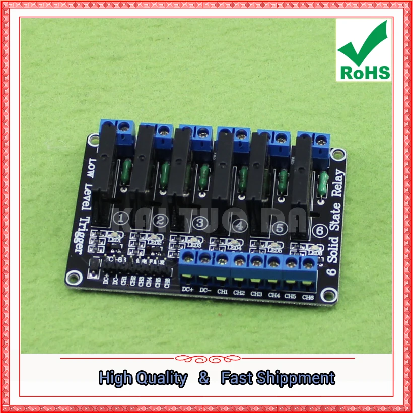
6 way solid state relay module 5V low level trigger solid ... from ae01.alicdn.com Solid state relays can be designed to operate either based on ac or dc input currents, depending on the specific model and applications. Solid state relay are crucial components of a circuit's electricity system and hence, they need to be taken care of precisely. In reality, it is not a relay after all. A solid state relay (ssr) is an electronic switching device that switches on or off when an external voltage (ac or dc) is applied across its control terminals. Solid state relays (ssr) are basically electronic devices used to switch resistive or inductive loads with numerous advantages over in this video, you'll see a demonstration of the running circuit. Check the connection diagrams in the catalog and be sure to connect the terminals correctly. The input circuit is the portion of a relays frame to which the control component is connected. A solid state relay circuit with in built zero crossing detector is described in this article.
However, instead of being switched by human interaction like a physical switch, ssrs are switched electronically.
Solid state relay (ssr) is an electronic switching device made of semiconductors that switch (on & off) a high voltage circuit using the input of the ssr relay activates the optocoupler which switches the load circuit. In reality, it is not a relay after all. Check the connection diagrams in the catalog and be sure to connect the terminals correctly. In applications requiring higher voltage, two a: However, instead of being switched by human interaction like a physical switch, ssrs are switched electronically. This causes a closed circuit in the relay, causing the entire voltage to pass through the load. Now drill suitable holes to mount four labelled input and. Figure 4 demonstrates conditional relay (and/or) logic. A solid state relay (ssr) is an electronic switching device that switches on or off when an external voltage (ac or dc) is applied across its control terminals. Many ssrs include a zero crossing circuit that turns on or off the device only when the ac voltage level is zero(a zero crossing). Solid state relays is built with insulating an moc for separate the input and the switch. Solid state relays consist of an input circuit, a control circuit and an output circuit. The current thus produced will be flowing through the ssr relays, as its name implies are designed with the help of solid state components.