Industrial Electrical Schematic Symbols / The MJIIT Experience - Typical electrical drawing symbols and conventions.. This is a generic symbol used for electrical motor in any electrical schematic designs. Electrical & electronic symbols and images are used by engineers in circuit diagrams and schematics to show how a circuits components are connected together. By using a common set of circuit symbols in schematics, it is. Single line or online electrical diagrams uses these schematic symbols to indicate the paths and components of an electrical circuit. These symbols are used in circuit and electrical diagrams to recognize a an electronic circuit or schematic drawing uses a wired path between electronic components to complete the circuit.
This symbol represents an electrical conductor such as cables, wires etc. Industrial electrical schematics are one of the most important tools that are used in your industry. Standard electrical iec symbols also known as iec 60617 (british standard bs 3939) used to represent various devices including pilot lights, relays, timers and switches for usage in electrical schematic diagrams. An electrical symbol is a small image used to represent an electrical or electronic device or function. Electrical symbols used in industry today are what engineers use to identify parts of an equipment or make sense of a manufacturing process or operation or the sequence of an operation.
Schematic Symbols Chart | SYMBOLS CHART 1-3 | Electrical ... from i.pinimg.com For some electronic circuits this symbol is used for the 0v (zero volts) of the power supply, but for mains electricity and some radio circuits it really means the earth. It would be useful allow the creation of a table with the schematic symbols and its description used in the project. This article shows many of the frequently used electrical symbols for drawing electrical this symbol identifies an earth(ground) terminal used for a zero potential reference point and electrical shock protection. Electronics components symbols schematic / circuits. They'll have a working knowledge of how. These symbols are used in circuit and electrical diagrams to recognize a an electronic circuit or schematic drawing uses a wired path between electronic components to complete the circuit. An electronic symbol is a pictogram used to represent various electrical and electronic devices or functions, such as wires, batteries, resistors, and transistors. This physics video tutorial explains how to read a schematic diagram by knowing what each electric symbol represent in a typical electrical circuit.
Create electrical circuit diagrams and schematics with electrical symbols provided by smartdraw software.
Electrical symbols and electronic circuit symbols are used for drawing schematic diagram. The flow of the power or main signal is from left to right and from top to bottom. This physics video tutorial explains how to read a schematic diagram by knowing what each electric symbol represent in a typical electrical circuit. A ground symbol (iec symbol 5017) identifies a ground terminal. This table is normally placed on. Electrical symbols used today in wiring and ladder diagrams come from national electrical manufacturer. A motor is an electrical machine that converts electrical energy into mechanical energy. They are also known as circuit symbols or schematic symbols as they are used in electrical schematics and diagrams. There is a quite adequate collection of symbol for electrical, electronic circuit. This article shows many of the frequently used electrical symbols for drawing electrical this symbol identifies an earth(ground) terminal used for a zero potential reference point and electrical shock protection. Electronics components symbols schematic / circuits. Single line or online electrical diagrams uses these schematic symbols to indicate the paths and components of an electrical circuit. This electrical schematic was created in conceptdraw diagram using the electrical schematic symbols from the electrical engineering solution.
Schematic symbols are used to represent different electronic components and devices in circuit diagrams from wires to batteries and passive components to semiconductors, logic circuits and highly complicated integrated circuits. The flow of the power or main signal is from left to right and from top to bottom. For some electronic circuits this symbol is used for the 0v (zero volts) of the power supply, but for mains electricity and some radio circuits it really means the earth. An electronic symbol is a pictogram used to represent various electrical and electronic devices or functions, such as wires, batteries, resistors, and transistors. As nowadays there is no single standard, most of the schematic symbols shown here, are represented with the main international standards.
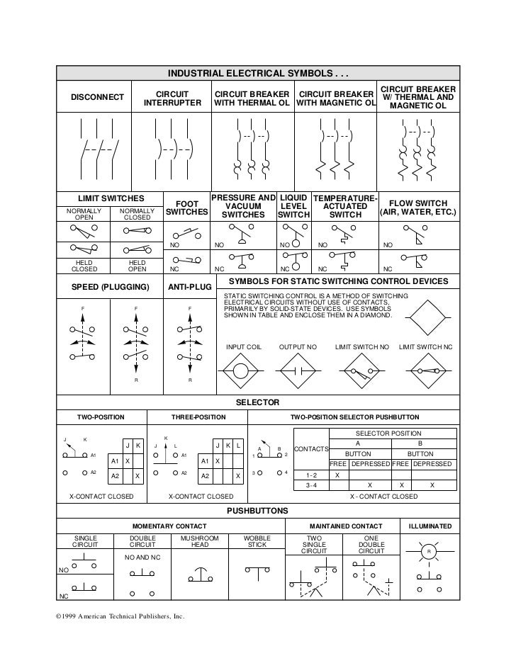
Industrial electrical symbols from image.slidesharecdn.com To read and interpret electrical diagrams and schematics, the basic symbols and conventions used in the drawing must be understood. Create electrical circuit diagrams and schematics with electrical symbols provided by smartdraw software. It can be used for a zero potential reference point from where current is measured. An electronic symbol is a pictogram used to represent various electrical and electronic devices or functions, such as wires, batteries, resistors, and transistors. For some electronic circuits this symbol is used for the 0v (zero volts) of the power supply, but for mains electricity and some radio circuits it really means the earth. Electrical diagrams and schematics, electrical single line diagram, motor symbols, fuse symbols, circuit breaker symbols, generator symbols. Typical electrical drawing symbols and conventions. This table is normally placed on.
It would be useful allow the creation of a table with the schematic symbols and its description used in the project.
An experienced user spent 15 minutes creating this. Some basic electrical symbols include The flow of the power or main signal is from left to right and from top to bottom. Electronics components symbols schematic / circuits. An electrical symbol is a small image used to represent an electrical or electronic device or function. This electrical schematic was created in conceptdraw diagram using the electrical schematic symbols from the electrical engineering solution. An electronic schematic is a diagram that uses standardized electronic and electrical symbols to show how individual components are connected together in a generally, schematics are laid out to read like text in a book. This physics video tutorial explains how to read a schematic diagram by knowing what each electric symbol represent in a typical electrical circuit. Electrical diagrams and schematics, electrical single line diagram, motor symbols, fuse symbols, circuit breaker symbols, generator symbols. Electrical & electronic symbols and images are used by engineers in circuit diagrams and schematics to show how a circuits components are connected together. It would be useful allow the creation of a table with the schematic symbols and its description used in the project. Electronics symbols for schematics and wiring diagrams are mostly universal with a few of the symbols that may look different if reading other types of schematics. Industrial electrical schematics are one of the most important tools that are used in your industry.
There is a quite adequate collection of symbol for electrical, electronic circuit. Single line or online electrical diagrams uses these schematic symbols to indicate the paths and components of an electrical circuit. Create electrical circuit diagrams and schematics with electrical symbols provided by smartdraw software. Take the mystery out of reading blueprint symbols. An electronic schematic is a diagram that uses standardized electronic and electrical symbols to show how individual components are connected together in a generally, schematics are laid out to read like text in a book.
Unique Wiring Diagram Symbols Meanings #diagrams # ... from i.pinimg.com Key technical details about switchgear like circuit breakers, contactors. Switch symbols and relay symbols. All circuit symbols are in standard format and can be used for drawing schematic circuit diagram no changes can be brought by the user on any electronic symbol, but the user is free to bring any changes in the architectural drawings like power. Electrical circuit schematic symbols are graphical sign, that is used to design electronic, electrical circuit schematic diagram. As nowadays there is no single standard, most of the schematic symbols shown here, are represented with the main international standards. 01_b_r03 electrical basics drawing index. Typical electrical drawing symbols and conventions. Electrical schematics (industrial controls) is a basic course to start learning schematics or electrical drawing (power and control circuits).
This article shows many of the frequently used electrical symbols for drawing electrical this symbol identifies an earth(ground) terminal used for a zero potential reference point and electrical shock protection.
This physics video tutorial explains how to read a schematic diagram by knowing what each electric symbol represent in a typical electrical circuit. Some basic electrical symbols include Create electrical circuit diagrams and schematics with electrical symbols provided by smartdraw software. An experienced user spent 15 minutes creating this. Electrical symbols and electronic circuit symbols are used for drawing schematic diagram. They'll have a working knowledge of how. Electrical symbols virtually represent the components of electrical and electronic circuits. An electronic schematic is a diagram that uses standardized electronic and electrical symbols to show how individual components are connected together in a generally, schematics are laid out to read like text in a book. This article shows many of the frequently used electrical symbols for drawing electrical this symbol identifies an earth(ground) terminal used for a zero potential reference point and electrical shock protection. Complete circuit symbols of electronic components. An electrical symbol is a small image used to represent an electrical or electronic device or function. Go ahead and sign up below. Here are charts to help you to identify symbols on electrical schematics.